Use the Vertex Editor to create intricate patterns. You can apply rounded corners to rectangles, convert an ellipse into a pie shape or arc or move the control points on a polygon or curve. Extrude operations let you rotate, scale, or move an object’s geometry in real time while appending duplicates of existing points.
The vertex editing operations that are available depend on the type of object that is selected.
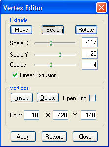
Use the Vertex Editor dialog box to set points in polygon and curve objects and create intricate designs.
After completing vertex editing operations, be sure to click either the Page Layout or Object Edit buttons.
You may open the Vertex Editor dialog box in any of the following ways:
Click the Edit Vertices button: in the Components Bar, and then click a polygon or curve object in the Work Window.
With a polygon or curve object selected in the Work Window, select Object>Resize.
With a title object that has been converted to a path selected, select Object>Resize.
On the Outline
Tab of the Quick Properties Editor dialog box, click the Edit
Vertices button: .
.
If using any of the preceding methods fails to open the Vertex Editor dialog box, select ObjectShow Vertex Editor.
Controls on the Vertex Editor dialog box include the following:
| Field/Control | Description |
| Extrude Move | Click to enter Extrude Move mode, which allows you to move the initial geometry across the origin while duplicating points. |
| Extrude Scale | Click to enter Extrude Scale mode, which allows you to scale the geometry around the origin while duplicating points. |
| Extrude Rotate | Click to enter Extrude Rotate mode, which allows you to rotate the geometry around the origin while duplicating points. |
| Move X, Move Y | With the Extrude function set in Move mode, use the sliders to change the direction and extent of the move horizontally and vertically (or enter numbers in the boxes).Move the origin to change the center of the scale operation. |
| Scale X, Scale Y | With the Extrude function set in Scale mode, use the slider to select the amount of the scale horizontally and vertically (or enter numbers in the boxes).Move the origin to change the center of the scale operation. |
| Angle | With the Extrude function set in Rotate mode, use the slider to select the number of degrees to rotate the geometry (or enter numbers in the boxes). Move the origin to change the center of the rotation. |
| Copies | Click and drag the slider to the right to select the number of copies of the geometry to be generated. Or, enter a number in the box. |
| Linear Extrusion | Click to checkmark to form the geometry and its copies into three-dimensional shapes along a linear path. |
| Insert | Click to add a new point ahead of the currently selected point (visible in red). |
| Delete | Click to delete the currently selected point (visible in red). |
| Open End | Click to checkmark to make the last point of the selected curve or polygon geometry unconnected to the first point, leaving it open. Click to un-checkmark to connect the last and first points of the selected curve or polygon geometry, closing it. |
| Point | Displays the order number of the currently selected point. |
| X | Displays the position along the horizontal axis of the currently selected point. |
| Y | Displays the position along the vertical axis of the currently selected point. |
| Save | Click to save the current changes. Restore will restore to last saved version or the original is no save was made. |
| Restore | Click to revert to the original (or last saved) version of the geometry. |
| Close | Click to cancel the operation and close the dialog box. |

